
Solid State Relays (SSRs) are fundamental components in modern electronic and industrial systems. Understanding their diagrams is not just technical knowledge it is a skill that enhances circuit design accuracy, efficiency, and reliability. Mastering SSR diagrams empowers engineers and technicians to design precise, safe, and high-performing circuits.
What is a Solid State Relay Diagram?
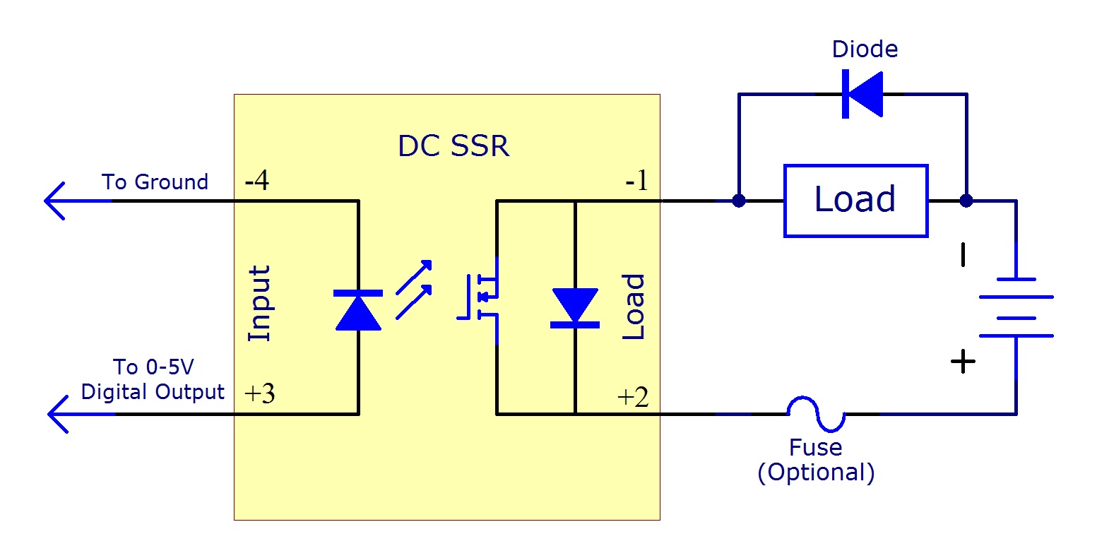
A solid state relay diagram is a schematic representation of how an SSR operates within a circuit. Unlike mechanical relays, SSRs use semiconductor devices to switch electrical loads without moving parts. Diagrams typically display the input trigger, isolation components, and output load connections, providing a visual roadmap of signal flow. A clear solid state relay diagram improves system understanding.
Key Elements of SSR Diagrams
- Input Section – Illustrates how low-voltage control signals activate the SSR.
- Opto-Isolation – Represents the separation between input and output for safety and noise reduction.
- Output Switching – Shows the semiconductor switches that control high-voltage loads.
- Indicator Signals – Optional LEDs or monitoring points that signal relay status.
Understanding these elements ensures that circuits are correctly connected, preventing errors and enhancing reliability.
Benefits of Studying SSR Diagrams
- Enhanced Design Accuracy – Knowing how each component interacts allows for precise circuit layouts and proper load handling.
- Improved Safety – Correct interpretation of opto-isolation and load connections reduces the risk of electrical hazards.
- Faster Troubleshooting – Clear diagrams make it easier to identify faulty connections or misconfigured components.
- Optimized Performance – Proper understanding ensures the SSR operates efficiently, extending the lifespan of both the relay and the connected devices.
Practical Tips for Leveraging SSR Diagrams
- Start with Basic Circuits – Familiarize yourself with simple SSR setups before moving to complex applications.
- Use Color-Coded References – Highlight input, output, and isolation sections for better visual clarity.
- Simulate Before Implementation – Virtual testing can prevent costly mistakes and reinforce diagram understanding.
- Regularly Review Standards – Electrical standards evolve; staying updated ensures designs are compliant and safe.
Why Diagram Mastery Matters
Mastering SSR diagrams is more than a technical requirement it is a cornerstone of efficient and reliable circuit design. Engineers who understand the flow of signals, isolation mechanisms, and switching actions can confidently create circuits that perform consistently under varied conditions. This knowledge also fosters innovation, as designers can adapt and optimize SSRs in new and creative ways.
Conclusion
Understanding solid state relay diagrams directly improves circuit design skills, safety, and efficiency. By studying key elements, following practical tips, and consistently applying this knowledge, engineers and technicians can achieve accurate, reliable, and high-performing circuits. Embracing this expertise is a significant step toward mastering modern electrical and industrial design practices.